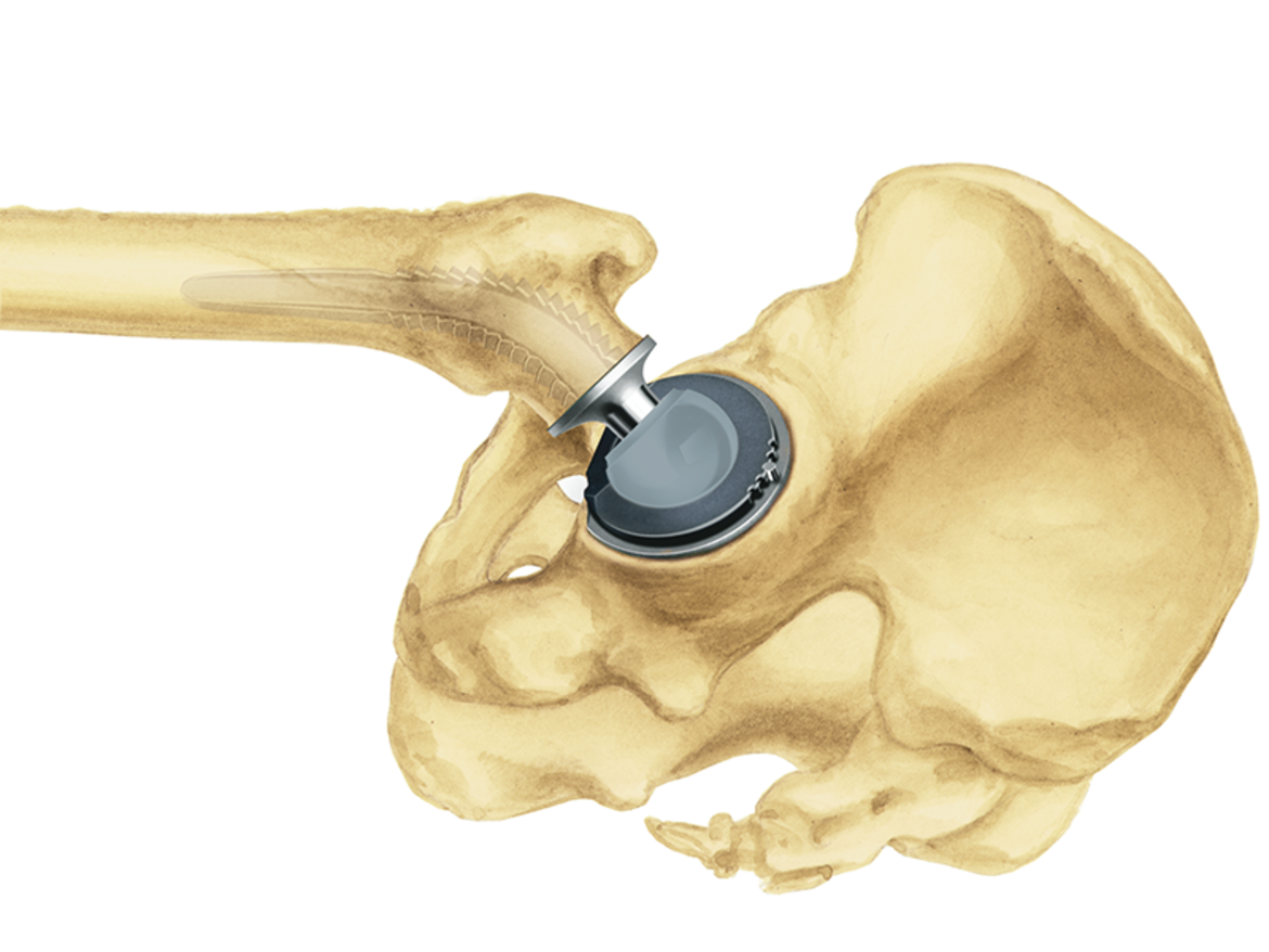
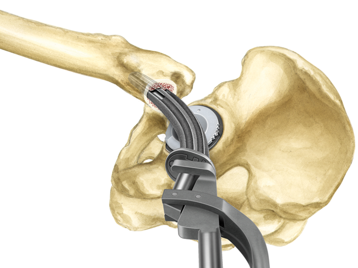
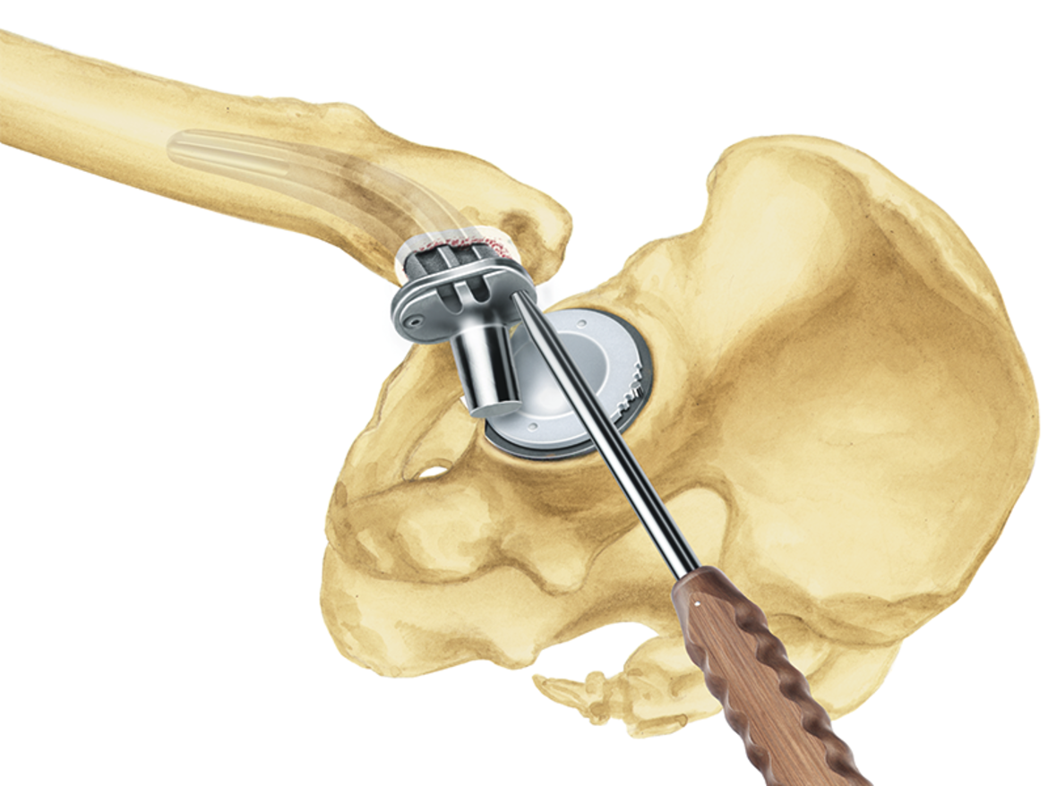
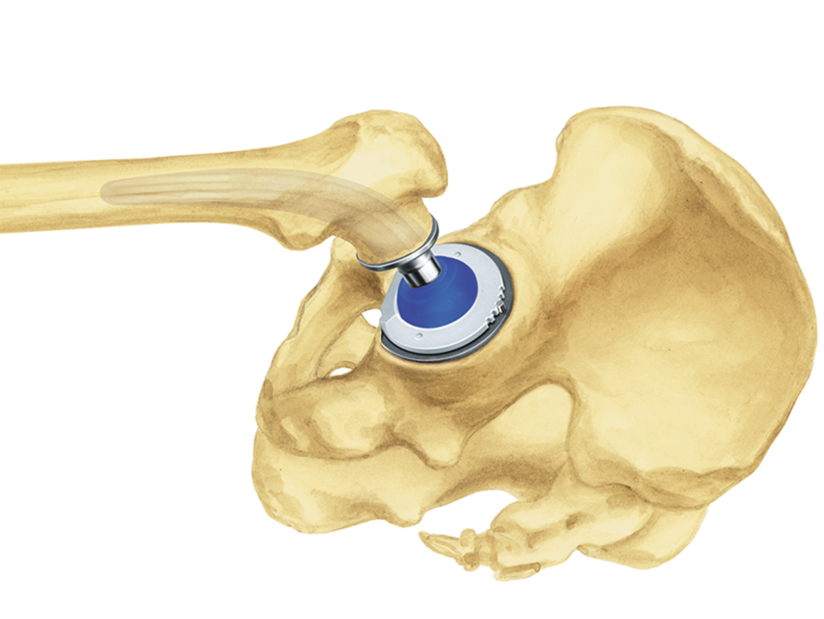
LINK SPII

Neutralizes torsional forces
The curved shape of the stem enables it to finds its way into the femoral canal, where it adapts perfectly to the anatomy.6 This means that stress peaks, as occur with three-point locking of straight shafts, are avoided and the stem has greater rotational stability.2
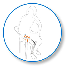
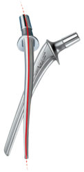
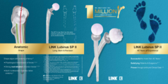
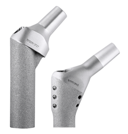
Developed in 1978, and available with a modular prosthesis head since 1984, this femoral stem was a great success and had a major influence on the principle of the anatomical hip prosthesis.1 The S‑shaped curvature, which follows the natural anatomy of the femur, has proved highly successful in this system. This has been repeatedly confirmed over the last 40 years in numerous publications, including the Swedish Hip Arthroplasty Register.1, 3 The outstanding clinical history was the reason for developing the ribbed prosthesis, the C.F.P. stem, and the SP-CL, based on the same principle.
Anatomical design
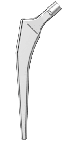
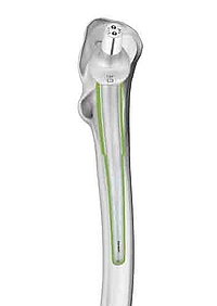
The anatomical shape of the stem enables it to fit centrally in the medullary canal. This helps to ensure a uniform cement coating, which can envelop the implant optimally.7 At the same time, anteroposterior and mediolateral ribs contribute to rotational stability.2, 8, 9, 10
Optimal anatomical reconstruction
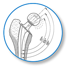
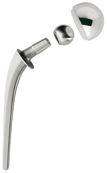
The SPII offers a system with great modularity. The multiplicity of possible variations in CCD angle, neck length, and stem length gives maximum flexibility for reconstruction of the anatomical structures in primary and revision arthroplasties. The stem tip is curved on the lateral side in order to prevent impacts when it is introduced into the medullary canal. The slender stem design meets all the requirements for minimally invasive, soft tissue, and bone-conserving implantation.
Successful long-term outcomes
Many long-term outcomes with survival rates of up to 92.3 percent after 23 years emphasize the success and great reliability of the SPII Stem.1
* www.odep.org.uk; Orthopaedic Data Evaluation Panel

- Kärrholm, Lindahl, Malchau, Mohaddes, Rogmark, Rolfson, ANNUAL REPORT 2015; The Swedish Hip Arthroplasty Register
- W.T. Stillwell. The Art of the Total Arthroplasty. Grune & Stratton, Inc. 1987; pp. 296
- H. Malchau et al; Prognosis of Total Hip Replacement, Orthopädie, Universität Göteborg, Schweden, 2002
- Malchau H, Herberts P, Ahnfelt L. Prognosis of total hip replacement in Sweden. Follow-up of 92.675 operations performed 1978-1990. Acta Orthop Scand 1993;64 (5): 497-506
- Garellick, Kärrholm, Rogmark, Rolfson, Herberts, ANNUAL REPORT 2014; The Swedish National Hip Arthroplasty Register.; p. 75
- Annaratone, Giovanni; Surace, Filippo Maria; Survival analysis of the cemented SPII stem; J Orthopaed Traumato (2000) 1:41-45. Springer Verlag
- LINK News Orthopädie aktuell, Spinger-Verlag GmbH & Co. KG, SPII® Modell Lubinus® - Stellenwert der SPII® Modell Lubinus® Hüftprothese im aktuellen Bericht des Nationalen Schwedischen Hüft-TEP-Registers von 1979 - 2002
- Langhans, M., Hofman, D., Ecke, H., & Nietert, M. (1992). Der Einfluß der Formgebung des Prothesenschaftes auf die Beanspruchung des proximalen Femurs. Unfallchirurgie, 18(5), pp. 266-273.
- Noble, P., Alexander, J., Lindahl, L., Yew, D., Granberry, W., & Tullos, H. (1988). The anatomic basis of femoral component design. Clinical Orthopaedics and Related Research(235), pp. 148-165.
- Denaro, V., & Fornasier, V. (2000). Fill, fit and conformation - an anatomical and morphometric study of a hip component in total hip arthroplasty (Rippen-Link). European Journal of Orthopaedic Surgery & Traumatology, 10(4), pp. 239-247.
- High risk of early periprosthetic fracture after primary hip arthoplasty in elderly patients using a cemented, tapered, polished stem: An observational, prospective cohort o study on 1,403 hips with 47 fractures after a mean follow-up time of 4 years· Broden C, Mukka S, Muren O, Eisler Stark A, Skoldenberg O, Acta Orthopaedica 2015; 86 (1):x-x
LINK SP-CL

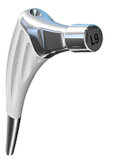
Developed for physiological force transmission
Metaphyseal fixation of the SP-CL is assisted by the HX coating (CaP).8 At the same time, the polished distal stem region protects against thigh pain.9,10 Medially the SP-CL rests along the length of the calcar (Shenton’s line) and is intended to promote a physiological distribution of forces.
Reduced stress shielding
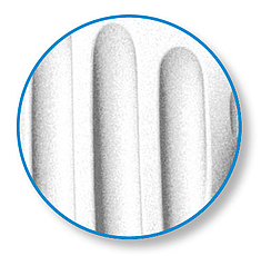
The successful ribbed structure provides initial fixation in the compressed cancellous bone. This makes it possible to achieve a design elasticity in spite of the proven “fit and fill” principle in the proximal femur. Thus the ribs not only provide high primary stability,7 but in combination with the LINK Tilastan- S alloy, they also achieve double elasticity. This can lead to a reduction in “stress shielding”.1
Bone preserving
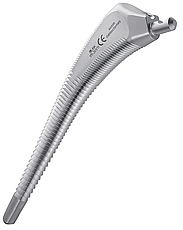
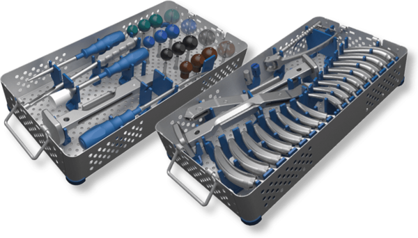
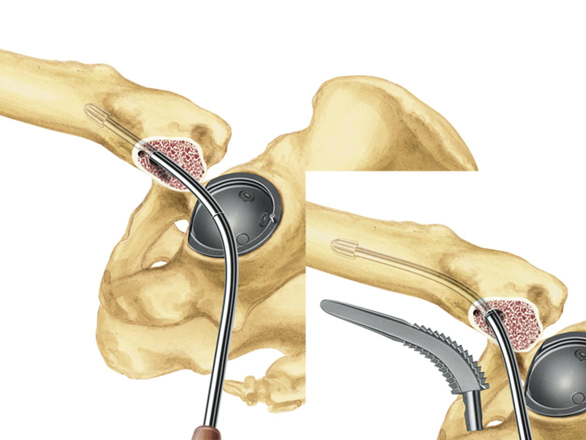
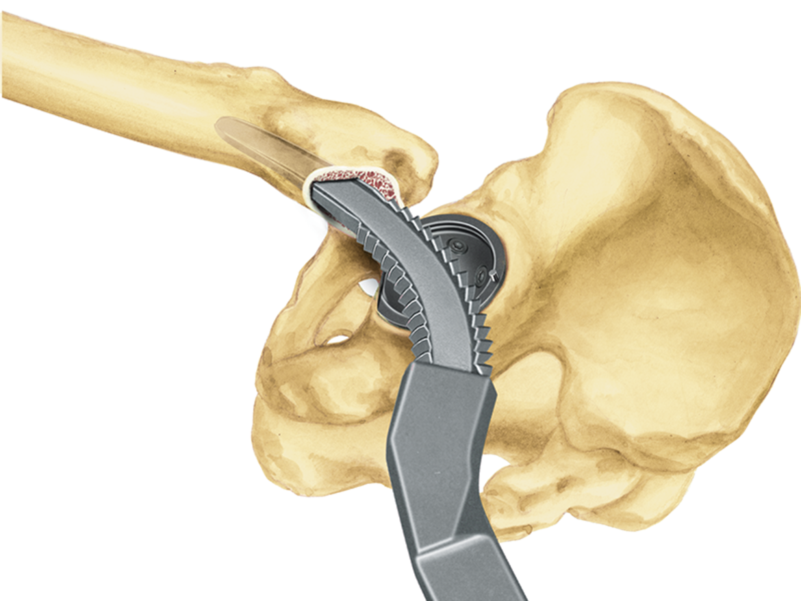
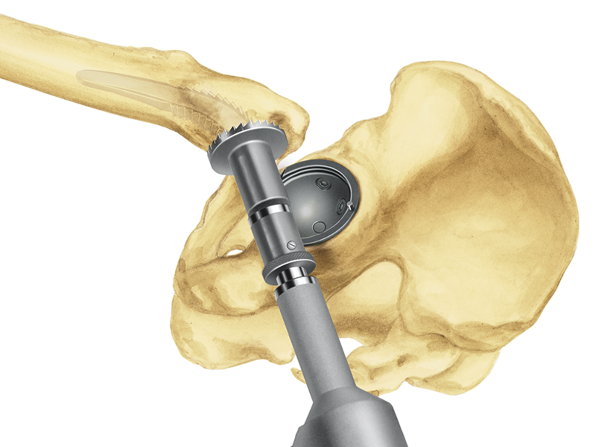
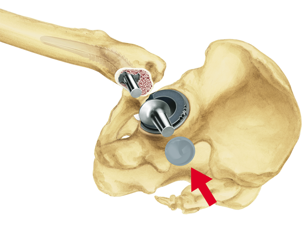
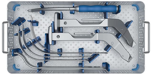
Anatomically shaped stems necessitate anatomically shaped instruments. The compressors in the SP-CL System follow exactly the anatomical design of the stems and prepare the bone bed for the SP-CL stem according to the natural contours of the intramedullary canal in the proximal femur.
While the flat, lateral implant profile is designed to protect the greater trochanter during implantation, cancellous bone compressors help to preserve valuable bone substance during resection.11
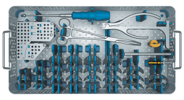
The compact, ergonomically designed instrument set permits effective, smooth intraoperative working.12
Proven design
The LINK SP-CL Hip Prosthesis System, with its anatomical, cementless design and its different versions, is aimed at the treatment of a wide range of patients. In order to meet the heavy demands put on the implants in a special way, the femoral components consistently follow the principle of the anatomical stem shape4, which has been in successful use for decades.
The anatomical S-shape helps to reduce stress peaks, which are a familiar problem with three-point fixation of straight stems. At the same time, it gives the implant greater rotational stability.1,5, 6

- Langhans, M., Hofman, D., Ecke, H., & Nietert, M. (1992). Der Einfluß der Formgebung des Prothesenschaftes auf die Beanspruchung des proximalen Femurs. Unfallchirurgie, 18(5), pp. 266-273.
- Schill S, Thabe H. (2000). Long- and Mid-Term Results of the Cementless Link Prosthetic System in Combination with the Ribbed Stem and Screw-in Cup, Type "V". Orthopädische Praxis, 36, pp. 160-167.
- Thabe H, Wolfram U, Schill S. (1993). Medium-term results using the cement-free link endoprosthesis. Ribbed shaft V socket. Zeitschrift fur Orthopädie und ihre Grenzgebiete, 131(6), pp. 568-573.
- Annual Report 2016; Swedish Hip Arthroplasty Register; www.shpr.se
- Noble, P., Alexander, J., Lindahl, L., Yew, D., Granberry, W., & Tullos, H. (1988). The anatomic basis of femoral component design. Clinical Orthopaedics and Related Research(235), pp. 148-165.
- Denaro, V., & Fornasier, V. (2000). Fill, fit and conformation - an anatomical and morphometric study of a hip component in total hip arthroplasty (Rippen-Link). European Journal of Orthopaedic Surgery & Traumatology, 10(4), pp. 239-247.
- Pipino, F., Keller, A. (2006). Tissue-sparing surgery: 25 years’ experience with femoral neck preserving hip arthroplasty. Journal of Orthopaedics and Traumatology, 7(1), pp. 36-41.
- Palm, L., Jacobsson, S., & Ivarsson, I. (2002). Hydroxyapatite coating improves 8- to 10-year performance of the link RS cementless femoral stem. The Journal of Arthroplasty, 17(2), pp. 172-175.
- Petrou, G., Gavras, M., Diamantopoulos, M., Kapetsis, T., Kremmydas, N., & Kouzoupis, A. (1994). Uncemented total hip replacements and thigh pain. Archives of Orthopaedic and Trauma Surgery, 113(6), pp. 322-326.
- Khanuja, H., Vakil, J., Goddard, M., & Mont, M. (2011). Cementless femoral fixation in total hip arthroplasty. The Journal of Bone & Joint Surgery, 93(5), pp. 500-509.
- DiGiovanni, C.W., Garvin, K.L., Pellicci, P.M. (1999). Femoral preparation in cemented total hip arthroplasty: reaming or broaching? Journal of the American Academy of Orthopaedic Surgeons, 7(6), pp.349-357.
- Internal document W. Link (DOC-05042)
C.F.P. II Hip System


LINK is one of the pioneers of anatomical and neck preserving prosthesis designs and has decades of experience in the development of these stem types.
The C.F.P.* stem which was introduced in 1998, has since then strongly marked the further development in the world of short stems. Today we are looking back at an impressive track record with survival rates of up to 98,3 % after 11 years.1
In the C.F.P. II stem this legacy continues by taking clinically proven design features and combining them with today’s requirements of a modern short stem.
The specific implant and instrument design conserves bone and soft tissue and adapts to the natural anatomy of the femur.2 Therefore the C.F.P. II equally lives up to its name and embodies our anatomical principles of bone preservation and “anatomy defines shape”.
The system is accompanied by a compact, ergonomic instrument set, which enables the surgeon to perform the arthroplasty smoothly and efficiently, regardless of the favored surgical approach.
* Collum Femoris Preserving
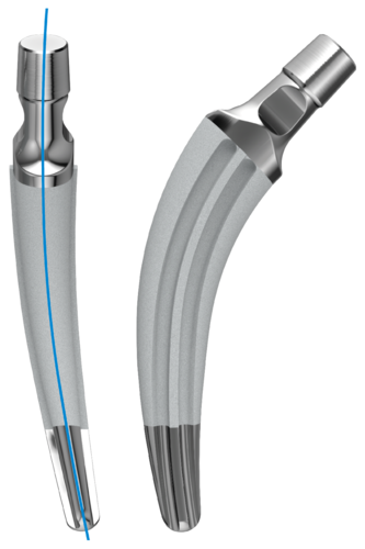
Anatomical Implant Design
The anatomical shape adapts to the natural femoral anatomy and effectively reduces stress risers.4, 5, 6
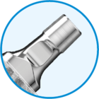
Polished and flattened neck
for higher ROM and less wear.
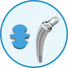
Ribbed profile for excellent primary
and secondary stability
The clinically proven ribbed structure serves to anchor the stem in the compressed cancellous bone and provides high primary and secondary stability.4, 9, 10
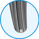
Tapered, rounded distal tip
The distal stem section facilitates implantation while also reducing the incidence of thigh pain, which can be caused by intramedullary fixation of a hip implant.11, 12

LINK HX (CaP) coating
The osteoconductive surface promotes bone ongrowth.7
LINK HX (CaP) Coating -
Surface Technology for Long Term Fixation
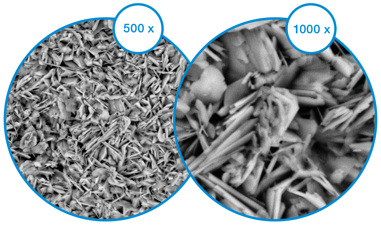
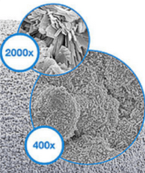
The HX-Coating is an osteoconductive CaP coating, approximately 15 μm thick which is applied in an electrochemical process. Due to the ultra-thin and highly soluble HX overcoat, the porous cell structure of the underlying substrate is retained open. This promotes osteoconduction and allows a stable osseointegration for secondary stability.7
Anatomical Compressor Design
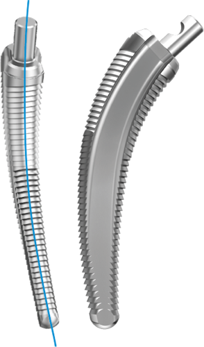
Anatomically shaped stems require anatomically shaped instruments. The compressors of the C.F.P. II system strictly follow the anatomical stem design.

High fixation zones
Concave AP cross section for maximum bone preservation and engagement of the proximal ribs.

Press-fit
The compressors and implants are matched to provide optimal press-fit.
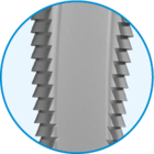
Terrace profile of the compressors
The C.F.P. II stem is anchored in a bed of compacted cancellous bone. The teeth of the compressors ensure that the cancellous substance is firmly compacted.3, 8
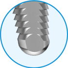
Rounded distal tip
Safe guidance and to avoid via falsa.
- Kendoff D, Citak M, Egidy CC, O'Loughlin PF, Gehrke T. (2013). Eleven-year results of the anatomic coated CFP stem in primary total hip arthroplasty. Journal of Arthroplasty, 28(6), pp. 1047-51.
- Vidalain, J. P., et al. (2011). The Corail Hip System. A practical approach based on 25 years of experience. Springer Heidelberg. pp. 54.
- Pipino, F., Keller, A. (2006). Tissue-sparing surgery: 25 years’ experience with femoral neck preserving hip arthroplasty. Journal of Orthopaedics and Traumatology, 7(1), pp. 36-41.
- Langhans, M., Hofman, D., Ecke, H., & Nietert, M. (1992). Der Einfluß der Formgebung des Prothesenschaftes auf die Beanspruchung des proximalen Femurs. Unfallchirurgie, 18(5), pp. 266-273.
- Noble, P., Alexander, J., Lindahl, L., Yew, D., Granberry, W., & Tullos, H. (1988). The anatomic basis of femoral component design. Clinical Orthopaedics and Related Research (235), pp. 148-165.
- Denaro, V., & Fornasier, V. (2000). Fill, fit and conformation - an anatomical and morphometric study of a hip component in total hip arthroplasty (Rippen-Link). European Journal of Orthopaedic Surgery & Traumatology, 10(4), pp. 239-247.
- Palm, L., Jacobsson, S., & Ivarsson, I. (2002). Hydroxyapatite coating improves 8- to 10-year performance of the link RS cementless femoral stem. The Journal of Arthroplasty, 17(2), pp. 172-175.
- DiGiovanni, C.W., Garvin, K.L., Pellicci, P.M. (1999). Femoral preparation in cemented total hip arthroplasty: reaming or broaching? Journal of the American Academy of Orthopaedic Surgeons, 7(6), pp.349-357.
- Schill S, Thabe H. (2000). Long- and Mid-Term Results of the Cementless Link Prosthetic System in Combination with the Ribbed Stem and Screw-in Cup, Type “V”. Orthopädische Praxis, 36, pp. 160-167.
- Thabe H, Wolfram U, Schill S. (1993). Medium-term results using the cement-free link endoprosthesis. Ribbed shaft V socket. Zeitschrift fur Orthopädie und ihre Grenzgebiete, 131(6), pp. 568-573.
- Petrou, G., Gavras, M., Diamantopoulos, M., Kapetsis, T., Kremmydas, N., & Kouzoupis, A. (1994). Uncemented total hip replacements and thigh pain. Archives of Orthopaedic and Trauma Surgery, 113(6), pp. 322-326.
- Khanuja, H., Vakil, J., Goddard, M., & Mont, M. (2011). Cementless femoral fixation in total hip arthroplasty.
The Journal of Bone & Joint Surgery, 93(5), pp. 500-509.
LINK C.F.P. Hip Prosthesis

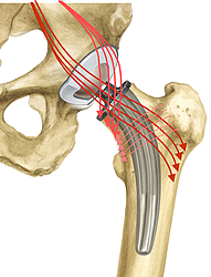
Physiological force transmission
Two different stem curvatures allow adaptation to the individual patient’s anatomy - for extended support of the implant on the Shenton’s line. The successful ribbed structure provides secure, rotationally stable fixation in the compressed cancellous bone.4, 5
Femoral neck-preserving, bioharmonic hip prosthesis
The C.F.P. Hip Prosthesis Stem enables femoral neck-preserving, cementless implantation. It was developed specifically for young, active patients, whose long life expectancy means that they are more likely than older patients to experience aseptic loosening with a conventional hip prosthesis.
The design of the C.F.P. Hip Prosthesis Stem incorporates biomechanical loading and anchoring principles, conforming to the hip anatomy and physiology. This ensures stable, stress-resistant anchoring of the prosthesis.3
The bone-preserving resection, preserving the femoral neck, creates favorable conditions for later interventions.
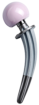
Reduced stress shielding
The pronounced ribbed profile and the LINK Tilastan alloy give the stem a high level of structural and material-based elasticity compared to other hip systems. This in turn minimizes femoral stiffness, thereby reducing “stress shielding”.6
Successful long-term outcomes
Many long-term outcomes with survival rates of up to 98.3 percent after 11 years emphasize the success and great reliability of the C.F.P. stem.3
Latest ODEP ratings can be found at www.odep.org.uk
- Prendergast, P., & Taylor, D. (1990). Stress analysis of the proximo-medial femur after total hip replacement. Journal of Biomedical Science, 12(5), pp. 379-382.
- Keaveny, T., & Bartel, D. (1993). Effects of porous coating and collar support on early load transfer for a cementless hip prosthesis. Journal of Biomechanics, 26(10), pp. 1205-1216.
- Kendoff, D., Citak, M., Egidy, C., O'Loughlin, P., & Gehrke, T. (2013). Eleven-year results of the anatomic coated CFP stem in primary total hip arthroplasty. The Journal of Arthroplasty, 28(6), pp. 1047-1051.
- Noble, P., Alexander, J., Lindahl, L., Yew, D., Granberry, W., & Tullos, H. (1988). The anatomic basis of femoral component design. Clinical Orthopaedics and Related Research(235), pp. 148-165.
- Denaro, V., & Fornasier, V. (2000). Fill, fit and conformation - an anatomical and morphometric study of a hip component in total hip arthroplasty (Rippen-Link). European Journal of Orthopaedic Surgery & Traumatology, 10(4), pp. 239-247.
- Langhans, M., Hofman, D., Ecke, H., & Nietert, M. (1992). Der Einfluß der Formgebung des Prothesenschaftes auf die Beanspruchung des proximalen Femurs. Unfallchirurgie, 18(5), pp. 266-273.
LCU

The LCU Hip System offers a cemented and a cementless hip stem. The cementless version is available with a HX coating or a PoroLink (microporous) surface. All versions follow the concept of a straight stem with tapered lateral shoulder. The profile is straight with a rectangular cross-section.
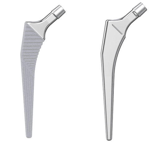
For all different stem types of the LCU Hip System the same set of instruments is used, which allows for intraoperative flexibility.
Two offset types allow for adaption to the patient’s anatomy 2:
- Standard type with a CCD angle of 130º
- Lateralizing type with a CCD angle of 125º
The stability of the implant is additionally enhanced by the characteristic metaphyseal V-shape, while the rectangular cross-section neutralizes torsional forces.5, 6, 8
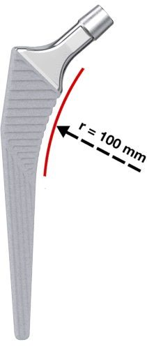
- Meta-diaphyseal support and fixation provided by a large medial curvature with a 100 mm radius for anatomical adaptation. For the cementless version, this is the prerequisite for primary and secondary stability.
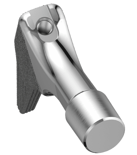
The flat, tapered prosthesis neck allows a large range of motion between prosthesis stem and acetabular cup.2
The 12/14 mm taper is designed for the use of modular LINK prosthesis heads made of ceramic or metal with various lengths and diameters.
Furthermore, the highly polished neck region reduces abrasion in the event of unintentional contact with the acetabular cup.9
Cementless Version
The stem is made from Tilastan-S (Ti6Al4V).
The micro-roughness of the metal surface is created by corundum-blasting, which produces an even and uniform surface structure with pore sizes and roughness values for osseointegration.2, 3
The HX coating with a thickness of 20 +/- 10 µm is applied by LEP (LINK Electrochemical Process) to the entire length of the prosthesis, and promotes bone ongrowth.4
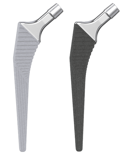
The horizontal ribs in the proximal section of the stem serve to counteract subsidence of the stem and to promote primary stability. The distal region has vertical ribs to counteract the rotational forces.7
- General information on Corail-type femoral stems: Hallan, G., et al. "Medium-and long-term performance of 11 516 uncemented primary femoral stems from the Norwegian arthroplasty register." Bone & Joint Journal 89.12 (2007): 1574-1580."
- Internal documentation W. LINK
- Garcia-Rey E, Garcia-Cimbrelo E. Grit-Blasted Implant Bone Interface in Total Joint Arthroplasty. In: Karachalios T, editor. Bone-Implant Interface in Orthopedic Surgery: Basic Science to Clinical Applications. London: Springer; 2014. p. 83-9.
- Yang C., Effect of calcium phosphate surface coating on bone ingrowth onto porous-surfaced titanium alloy implants in rabbit tibiae, J Oral Maxillofac Surg. 2002 Apr;60(4):422-5.
- Hwang KT, Kim YH, Kim YS, Choi IY. Total hip arthroplasty using cementless grit-blasted femoral component: a minimum 10-year follow-up study. The Journal of arthroplasty. 2012;27(8):1554-61.
- Jones DL, Westby MD, Greidanus N, Johanson NA, Krebs DE, Robins L, et al. Update on Hip and Knee Arthroplasty: Current State of Evidence. Arthritis care & research. 2005;53:772-80.
- Vidalain, Jean-Pierre. Twenty-year results of the cementless Corail stem. International orthopaedics, 2011, 35. year, No. 2, p. 189-194.
- Khanuja H, Vakil J, Goddard M, Mont M. Current Concepts Review: Cementless Femoral Fixation in Total Hip Arthroplasty. J Bone Joint Surg Am. 2011;93:500-9.
- International Orthopedics, Volume 41, Number 3, March 2017, Page 611-618
- (Scheerlinck, T., and P-P. Casteleyn. "The design features of cemented femoral hip implants." Bone & Joint Journal 88.11 (2006): 1409-1418.)
3C

Philosophy
The 3C hip system employs a straight stem with tapered lateral shoulder, tapered lateral distal stem and proximal coating to encourage proximal bone ingrowth.
The profile is straight with a wide proximal M-L dimension to give the implant stability against rotational forces and protects against sinking.
Two stem types for cemented and cementless stems, as well as a short version of the cementless stems allow for optimal adaption to the patients anatomy and bone quality
- Standard stem type with a CCD angle of 131º
- Lateralizing stem type with a CCD angle of 127,5º
- No vertical drop difference
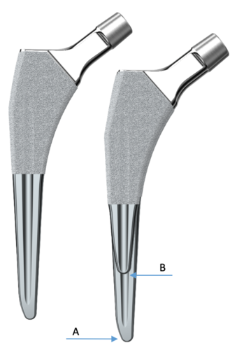
The short (B) version is a shortened standard (A) stem. The cemented version is one size down from the cementless stem. This features allow to implant a short, standard cementless or cemented stem with the same surgical technique, or for a intraoperative change between the 3C variants.
Materials
The following materials and coatings are used for 3C hip stems:
- The cemented stem is made from EndoDur-S (forged CoCrMo)
- The cementless stem is made from Tilastan-S (forged Ti6Al4V alloy)
- Micro-roughness of the stem’s surface ensures primary fixation and is available in PlasmaLink and osteoconductive double coating made from titanium plasma and calcium phosphate (TiCaP)1
This produces a regular and uniform micro structure surface. The distal stem is smooth to discourage bone integration.
Biomechanical properties
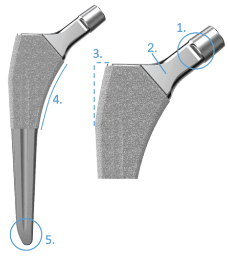
- Flattened tapered neck increases the range of motion between stem and acetabular cup
- The highly polished neck area reduces the abrasion of the polyethylene insert if contact should occur2
- Tapered lateral shoulder of the stem allows the trochanter major to remain intact while still providing a wide proximal M-L dimension of the implant
- Allows direct anterior approach
- Large anatomical medial curvature provides metaphyseal support, fixation and load transfer. Additionally it ensures good anatomical fit, essential for primary and long term stability
- Tapered distal end prevents bone contact
- For the standard length this facilitates introduction of the stem into the medullary cavity
Lubinus Classic Plus

Rapid postoperative mobilization
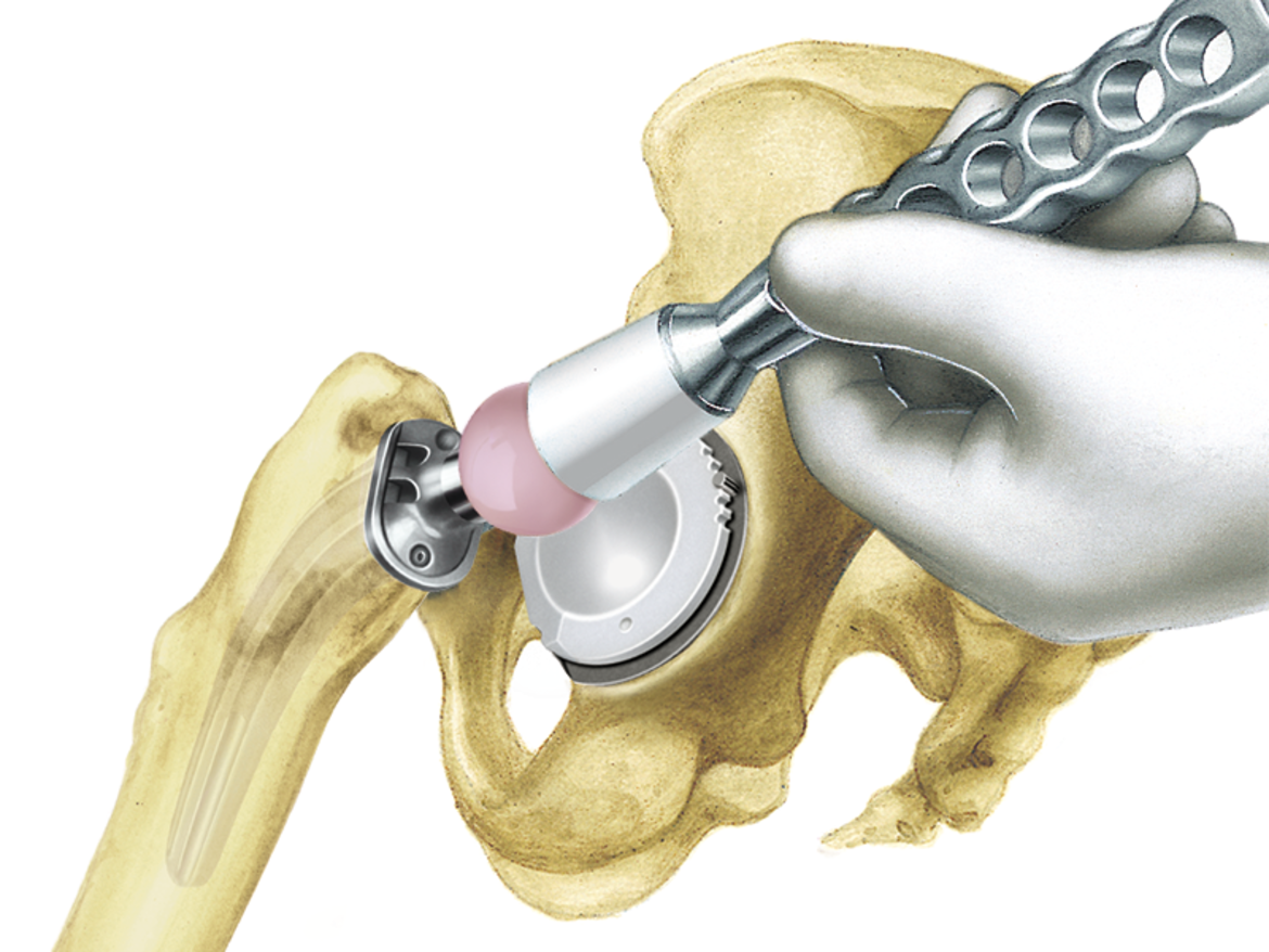
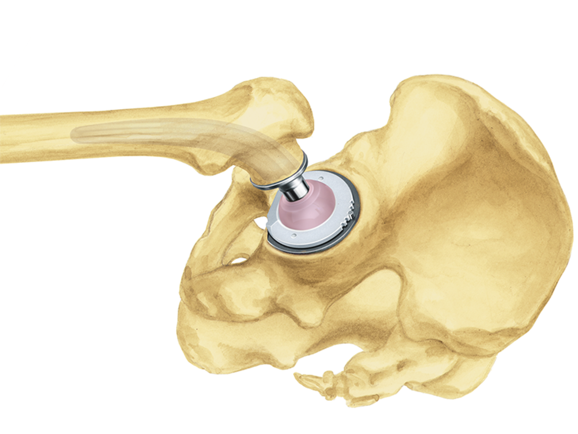
The cemented placement makes the hip prosthesis system particularly suitable for elderly patients for whom cementless placement is not a possibility. The direct stability of the stem and acetabular cup in the cement coating permits rapid postoperative mobilization of the patient. This, in turn, means shorter recovery times and shorter hospitalization for the patient.2
The 126° CCD angle was also chosen with elderly patients in mind. This reflects the physiological change of the angle with increasing age.2
In combination with the LINK IP Polyethylene Acetabular Cup, LINK Lubinus Polyethylene Acetabular Cup, or the LINK Vario Cup, this system offers outstanding cemented hip replacement.
Physiological force transmission
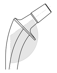
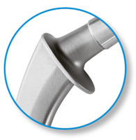
The stem, which is made of a cobalt chrome alloy, has a simple but clinically proven design.1 Wide, rounded surfaces on the medial and lateral side serve to protect the cement bed. The large prosthesis collar enables proximal, bioharmonic force transmission. The collar counteracts sintering of the stem.3
- Annual Report 2002, Swedish Hip Arthroplasty Register, www.shpr.se*
- L. Claes, P. Kirschner, C. Perka and M. Rudert, AE-Manual der Endoprothetik - Hüfte und Hüftrevision, Heidelberg Dordrecht London New York: Springer, 2012.
- Fröen JF, Lund-Larsen F., Lubinus Interplanta total hip arthroplasties, Tidsskr Nor Loegeforen 1998; 118: 2767-71*
*This data relates to the IP stem, the predecessor of the Lubinus Classic Plus Prosthesis.
LINK MP Reconstruction System

The LINK MP Reconstruction System gives the surgeon the intraoperative flexibility and certainty1 that is essential for a successful revision procedure with pronounced bone loss. The system’s unique design has produced outstanding outcomes for decades.2, 3, 4
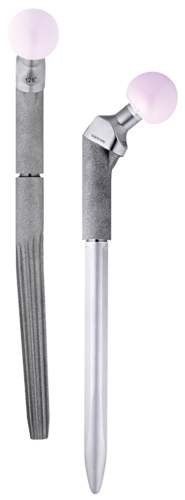
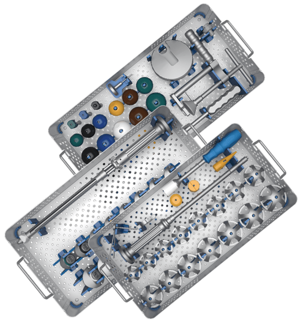
With just three instrument trays, the MP System enables a simple and fast surgery and a smooth process in five steps. The modular system gives the surgeon a high degree of flexibility in terms of adapting leg length, offset, and anteversion, independently of the distal cementless or cemented anchoring of the stem. This permits a quick and uncomplicated intraoperative response to the individual anatomy and defect.5
The stems in all six lengths have a 3° angulation, which facilitates following the anatomical curvature of the femur. The 2° tapered stem with peripheral longitudinal ribs gives outstanding stability in the femur, even with large proximal defects.2
The cemented stems can also provide secure fixation when the bone quality is poor.
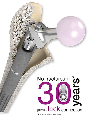
The PowerLock toothed connection allows the stem length to be adjusted intraoperatively by means of spacers in 10 mm increments up to 30 mm for revision arthroplasties. The absence of a taper connection means that the stem length and also the anteversion and offset can be adjusted retrospectively without endangering the distal fixation of the stem.
- Postak PD, Greenwald AS: The Influence of Modularity on the Endurance Performance of the LINK® MP® Hip Stem. Orthopaedic Research Laboratories, Cleveland, OH, 2001
- Rodriguez, J. A., et al., et al. Reproducible fixation with tapered, fluted, modular, titanium stem in revision hip arthroplasty at 8-15 years follow-up. The Journal of Arthroplasty. 2014, 29.;
- Kwong LM, Miller JA, Lubinus P: A Modular Distal Fixation Option for Proximal Bone Loss in Revision Total Hip Arthroplasty. J Arthroplasty Vol. 18 No. 3 Suppl. 1 2003
- Klauser et al. - Medium-term Follow-Up of a Modular Tapered Noncemented Titanium Stem in Revision Total Hip Arthroplasty, The Journal of Arthroplasty Vol 28 No. 1, 2013, 84-89)
- Internal documents (Complaint Reports and Competitors Comparison)
MP Monoblock

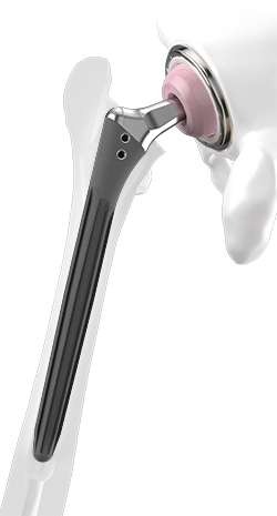
Going back to the proven design features of the MP Reconstruction System, the MP Monoblock is designed to meet the needs of modern revision surgery and is completing the MP Family with a new versatility. The MP 2° taper angle and the proven, broad spline geometry give the stem a superior axial stability and lower the risk of subsidence.1 The rough, grit blasted surface of the stem made from biocompatible Tilastan-S shall support the osseointegration and bone remodelling to provide long-term stability.2 Low risk of subsidence combined with a high offset version shall minimize the risk of luxation, while the short taper and flattened neck provide a great range of motion.1, 2, 3
The surgical technique and instrumentation provides wide intraoperative versatility. The result is a system that allows the surgeon unlimited flexibility within the MP family.4
The instruments are designed to create a precise, reproducible relationship between the reamer, trial and implant positioning to help predict the ideal centre of rotation and support long-term stability of the hip joint.4
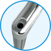
Guided insertion
fixed instrument connection
for full rotational control
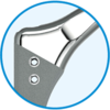
Suture holes
Ø 3mm suture holes
with smooth, polished edges
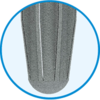
Rounded tip
The tips of the stems are rounded
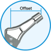
Neck portion
2 offset options & CCD angles
A/P flattened & polished neck
short 12/14 taper

Surface
PoroLink, rough, grit blasted
surface, 200x

Distal stem portion
2° taper in the distal portion
8 to 10 ribs with broad,
tapered geometry
- Pierson J, Small S, Rodriguez J, Kang M, Glassman A. The Effect of Taper Angle and Spline Geometry on the Initial Stability of Tapered, Splined Modular Titanium Stems. J Arthroplasty. 2015 Jul;30(7):1254-9
- Rodriguez et al. – Reproducible fixation with a tapered, fluted, modular, titanium stem in revision hip arthroplasy at 8-15 years follow-up, The Journal of Arthroplasty 29 Suppl. 2 (2014) 214-218 Berry – Treatment of Vancover B3 Periprosthetic Femur Fractures with a fluted tapered stem, clinical orthopaedic and related research Number 417, pp 224-231
- Dr. med. Martin Ellenrieder. Einfluss der Defektgröße des femoralen Knochenlagers auf die Primärstabilität modularer Revisionshüftstiele - eine biomechanische Analyse (Seite 16)
- Internal Document W. Link (DOC-10571)
MobileLink

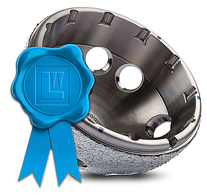
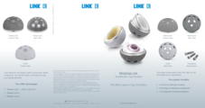
Many years of experience with successful implant systems and a range of fixation concepts, together with state-of-the-art material and coating technologies, have gone into the development of this new acetabular cup system. The result is the versatile cementless MobileLink Acetabular Cup System.
The MobileLink Acetabular Cup System comes in two different versions: A cluster-hole press-fit cup and a multi-hole press-fit cup. Both versions of the shells are available in a PlasmaLink, a TiCaP double coating or a TrabecuLink surface.
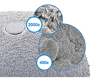
The TiCap double coating combines a porous surface for primary fixation with our osteoconductive2 HX calcium phosphate coating. This combination is designed to give optimal primary stability and osseointegration.
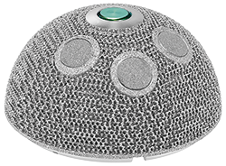
The 3-dimensional TrabecuLink structure, with its pore size, porosity and structure depth, also provides an excellent basis for promoting osteoconduction and microvascularization, taking into account the requirements for the structure-covering protein layer (fibronectin - vitronectin - fibrinogen).4,5
The MobileLink Acetabular Cup System can be used with ceramic or UHMWPE inserts. UHMWPE inserts are available in X-LINKed and E-DUR (X-LINKed, Vit-E PE) versions. All UHMWPE inserts are available in a standard version and also with protection against luxation. The MobileLink Acetabular Cup System can be combined with modular offset and/or inclining casing/insert adapters (Face Changer). The adapters allow restoration of the anatomy in revision cases. In addition, the adapters permit the use of ceramic inserts in revision arthroplasties.
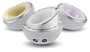
The MobileLink Acetabular Cup System can be transformed into a modular dual mobility system, with the use of Dual Mobility Inserts made from EndoDur. The DM insert is to accommodate poly DM liners from the BiMobile Dual Mobility System.
The Dual Mobility concept was developed by Prof. Gilles Bousquet in the 1970s with the aim of avoiding recurrent hip luxations. A modular Dual Mobility System is composed of a Dual Mobility Insert with a highly polished inner surface placed in a Shell in which a mobile polyethylene liner having a pressed in prosthesis head is moving.
Features and Advantages of Dual Mobility:
- Dual mobility leads to reduced risk of dislocation and increased range of motion (RoM) 6
- Polished inner surface for minimized wear and a prolonged implant life 7,8
- Self-centering Liner promotes even wear patterns and enhances dislocation resistance 9
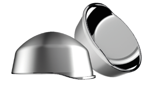
The 3-dimensional TrabecuLink structure, with its pore geometry (porosity: 70%, pore size: 610-820 μm, structure depth: up to 1 mm) ensures excellent cell ongrowth. 4,5,10
Pore filling
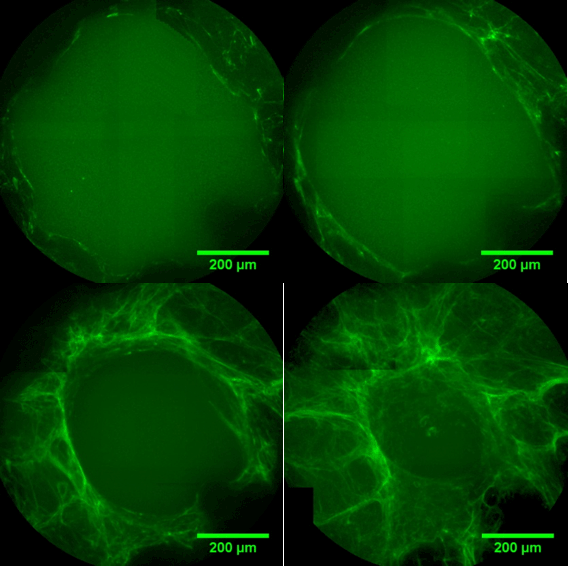
The sequence of images shows a pore of the TrabecuLink structure being filled with tissue under in-vitro cell culture conditions. The fibronectin laid down by human fibroblasts and continually reorganized over a period of eight days is visible as green fibers. Fibronectin is a component of the extracellular matrix that is formed at an early stage of the healing process. It forms a basis for the embedding of collagen, which is essential for mineralization of the tissue and ingrowth of bone into the structure. Apart from the accumulation of fibronectin, which increases over time, a clear contraction of the matrix towards the center of the pore can be observed. This contraction mechanism, which is attributable to the cellular forces acting in the tissue, accelerates the rate at which the pore is filled with tissue, compared to a layer-by-layer tissue growth (Reference: Joly P et al., PLOS One 2013; journals.plos.org/plosone/article. Julius Wolff Institute, Charité - Universitätsmedizin Berlin
Features and advantages
Wide choice of sizes (Ø 42-80 mm)
Choice of latest materials, such as E-DUR® Polyethylene
Clinically proven rough TiCaP® Double Coating 2
Secure – triple fixated inserts
Unique technology of the Face Changer fixation1,3
50/36 mm – small outside, large inside
Color coding for efficient work flow
High flexibility, minimal stock holding
Intraoperative flexibility
Simple instrument set and color coding for efficient surgical procedures
Casing/insert adapter (Face Changer) for anatomical reconstruction1
Variable options for placing bone screws 1
- Data on File, Waldemar Link.
- Ullmark G, Sorensen J, Nilsson O. Analysis of bone formation on porous and calcium phosphate-coated acetabular cups: a randomised clinical [18F]fluoride PET study. Hip international: the journal of clinical and experimental research on hip pathology and therapy. 2012;22(2):172-8.
- PCT-Patent Application WO 2017/140497 A1
- Cecile M. Bidan, Krishna P. Kommareddy, Monika Rumpler, Philip Kollmannsberger, Yves J.M. Brechet, Peter Fratzl, John W.C. Dunlop. et al.; How Linear Tension Converts to Curvature: Geometric Control of Bone Tissue Growth; PLoS ONE 7(5): e36336. doi.org/10.1371/journal.pone.0036336 (2012)
- Pascal Joly, Georg N. Duda, Martin Schöne, Petra B. Welzel, Uwe Freudenberg, Carsten Werner, Ansgar Petersen, et al.; Geometry-Driven Cell Organization Determines Tissue Growth in Scaffold Pores: Consequences for Fibronectin Organization; PLoS ONE 8(9): e73545. doi.org/10.1371/journal.pone.0073545 (2013)
- Stroh, D. Alex, et al. "Dual-mobility bearings: a review of the literature." Expert review of medical devices 9.1 (2012): 23-31.
- Long, M., & Rack, H. (1998). Titanium alloys in total joint replacement—a materials science perspective. Biomaterials, 19(18), 1621-1639
- Loving L, Herrera L, Banerjee S, Heffernan C, Nevelos J, Markel DC, Mont MA. 2015. Dual mobility beari ngs withstand loading from steeper cup-inclinations without substantial wear. J Orthop Res. 33(3):398-404.
- Fabry C, Kaehler M, Hermann S, Woernle C, Bader R. 2014. Dynamic behavior of tripolar hip endoprostheses under physiological conditions and their effect on stability. Medical Engineering & Physics 36:65– 71.
- Steinemann SG; Compatibility of Titanium in Soft and Hard Tissue – The Ultimate is Osseointegration; Materials for Medical Engineering, WILEY-VCH, Volume 2, Page 199-203
TrabecuLink Augments

The latest material and fixation technologies have been taken into account and used in the design of the TrabecuLink Augments.
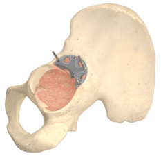
The TrabecuLink Augments offer an attractive solution in cases of segmental acetabular defects as a prosthetic alternative to structural allograft. The biocompatible material Tilastan-E1,2 and the TrabecuLink structure offer an excellent prerequisite for a stable and permanent treatment of bone defects.
Furthermore, the 3-dimensional TrabecuLink structure, with its pore size, porosity and structure depth, also provides an excellent basis for promoting osteoconduction and microvascularization, taking into account the requirements for the structure-covering protein layer (fibronectin - vitronectin - fibrinogen) 3,4.
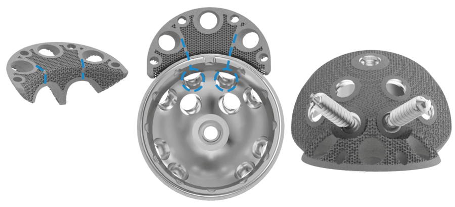
The Augments can be combined with all Link cups, in particular with the MobileLink cup, which has variable options for placing bone screws, as the Augment design allows flexibility to put bone screws through shell and Augment.
In case of acetabular defects the combination of a LINK shell with TrabecuLink Augments can be the solution to help conserve the natural patient anatomic and kinematics.
The Augment size range allows good fit for different anatomies and defects5.
Versatility
- The Augment size range allows good fit for different anatomies and defects5
- Variable bone screw angulation/options
- The Augment design allows flexibility to put bone screws through shell and Augment – big recesses allow for great variability in positing the Augment5
- Low Augment profile
- Augments can be used upside down as buttresses5
Effective fixation
- Sufficient grip of Augments. Augments have a great primary stability5
- Pore geometry of the TrabecuLink structure for effective cell ongrowth3,4,7
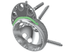
- Great connection between shell and Augment by application of cement mantle (according to surgical technique) 5,6
Reproducible surgical technique
- The Augment forceps helps to place the Augment5
- Temporary fixation of trial Augment and final Augment by drill pins through pin holes - pins which hold trial Augments in place help to position final implant5
- Small inventory
TrabecuLink
3-dimensional structure – for optimal bone ongrowth
- Pore geometry (porosity: 70%, pore size: 610-820 μm, structure depth: up to 1 mm) ensures excellent cell ongrowth 3,4,7
Pore filling
The sequence of images shows a pore of the TrabecuLink structure being filled with tissue under in-vitro cell culture conditions. The fibronectin laid down by human fibroblasts and continually reorganized over a period of eight days is visible as green fibers. Fibronectin is a component of the extracellular matrix that is formed at an early stage of the healing process. It forms a basis for the embedding of collagen, which is essential for mineralization of the tissue and ingrowth of bone into the structure. Apart from the accumulation of fibronectin, which increases over time, a clear contraction of the matrix towards the center of the pore can be observed. This contraction mechanism, which is attributable to the cellular forces acting in the tissue, accelerates the rate at which the pore is filled with tissue, compared to a layer-by-layer tissue growth (Reference: Joly P et al., PLOS One 2013; https://journals.plos.org/plosone/article?id=10.1371/journal.pone.0073545). Julius Wolff Institute, Charité - Universitätsmedizin Berlin

- Data on File, Waldemar Link.
- Wang, Hong, et al. "A comparison of biocompatibility of a titanium alloy fabricated by electron beam melting and selective laser melting." PloS one 11.7 (2016): e0158513
- Cecile M. Bidan, Krishna P. Kommareddy, Monika Rumpler, Philip Kollmannsberger, Yves J.M. Brechet, Peter Fratzl, John W.C. Dunlop et al. (2012) How Linear Tension Converts to Curvature: Geometric Control of Bone Tissue Growth. PLoS ONE 7(5): e36336
- Pascal Joly, Georg N. Duda, Martin Schöne, Petra B. Welzel, Uwe Freudenberg, Carsten Werner, Ansgar Petersen et al. (2013) Geometry-Driven Cell Organization Determines Tissue Growths in Scaffold Pores: Consequences for Fibronectin Organization. PLoS ONE 8(9): e73545. doi.org/10.1371/journal.pone.0073545
- Internal Document, Waldemar Link.
- Beckmann, N. A., et al. "Comparison of the stability of three fixation techniques between porous metal acetabular components and augments." Bone & Joint Research 7.4 (2018): 282-288.
- Steinemann SG: Compatibility of Titanium in Soft and Hard Tissue – The Ultimate is Osseointegration; Materials for Medical Engineering, WILEY-VCH, Volume 2, Page 199-203
BiMobile Dual Mobility System

Reliable – Safe – Solution
The concept of double mobility was developed by Prof. Gilles Bousquet in 1975, with the aim of treating recurrent hip luxations.13 The system consists of a metal casing with a highly polished internal surface and a movable polyethylene inlay, inside which a press-fitted prosthesis head moves. This provides a greater range of motion with less abrasion14, 15, 16 and reduced risk of luxation.15, 17, 18 It was on the basis of this principle that the BiMobile Acetabular Cup System came about.
The development of the bimobile acetabular cup system drew on many years of experience with successful implant systems and fixation concepts plus state-of-the-art material and coating technologies. The result is the versatile LINK BiMobile Acetabular Cup System.
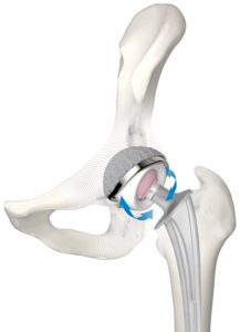
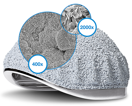
The cementless LINK BiMobile Acetabular Cup is available with a TiCaP double coating. The TiCaP double coating combines the properties of a highly porous layer of pure titanium for primary fixation and an osteoconductive3 calcium phosphate coating, which together provide optimal primary and secondary implant stability.4, 5 A supportive macrostructure on the cup equator increases the primary stability.9
Highly wear-resistant cup1, 2, 6
The Link BiMobile Dual Mobility System is available in two versions, either cemented or cementless. The metal casings in both versions are fabricated from biocompatible, sturdy EndoDur CoCrMo material.1, 2 The inner surface is highly polished in order to keep abrasion to a minimum.
Use of known anchoring techniques
The cemented BiMobile Acetabular Cup has a finely matt-finished SatinLink surface, which is also a feature of the SP II stems. Latitudinal and longitudinal groove-like structures reinforce the fixation and allow air to escape when the implant is pressed into the cement bed.
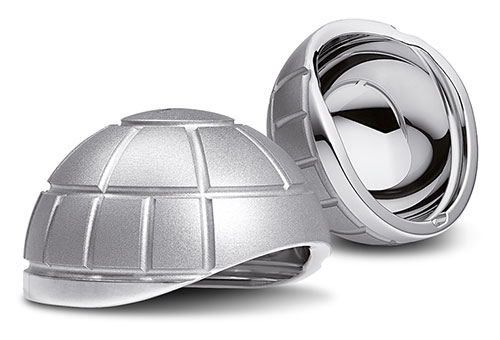
Self-centering inlay11
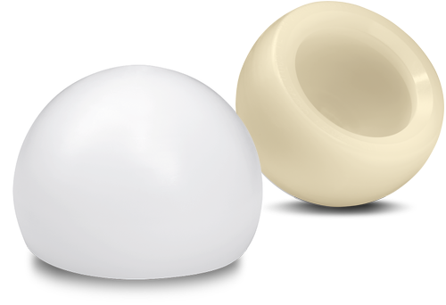
The inlays are available in UHMWPE and E-Dur (X-LINKed Vit-E PE) and can be combined with Link prosthesis heads made of CoCrMo or ceramic with a 22 or 28 mm diameter.
Features and advantages
Highly abrasion-resistant, biocompatible EndoDur CoCrMo material1, 2, 6
Safe implantation thanks to a fixed implant-instrument connection and unobstructed view of the acetabular cup rim11, 12
Cementless and cemented fixation
28 mm prosthesis heads starting at a cup size of 48 mm for a wide range of motion
Broad range of sizes (42–70 mm)
Clinically proven, very rough TiCaP double coating2, 3
Self-centering inlays for a uniform load distribution and increased protection against luxation7
Inlays available in Vit-E PE and UHMWPE
Anatomical medioventral recess for a wide range of motion and for protection of the femoral nerve and iliopsoas
Size-adapted clearance between liner and metal casing for constant articulation11
Intraoperative flexibility11, 12
- Internal document W. LINK (DOC-08614)
- Internal document W. LINK (DOC-08725)
- Ullmark G et al.: "Analysis of bone formation on porous and calcium phosphate-coated acetabular cups: a randomised clinical [18F] fluoride PET study." Hip International 22.2 (2012).
- Cunningham B W et al.: “General Principles of Total Disc Replacement Arthroplasty”, Spine, Vol. 28, No. 20 Suppl., 2003
- Bobyn, J. D., et al. „The optimum pore size for the fixation of porous-surfaced metal implants by the ingrowth of bone.“ Clinical orthopaedics and related research 150 (1980): 263-270.
- Long, M., & Rack, H. (1998). Titanium alloys in total joint replacement—a materials science perspective. Biomaterials, 19(18), 1621-1639.
- Fabry C, Kaehler M, Hermann S, Woernle C, Bader R. 2014. Dynamic behavior of tripolar hip endoprostheses under physiological conditions and their effect on stability. Medical Engineering & Physics 36:65- 71.
- Internal document W. LINK (DOC-08553)
- Internal document W. LINK (DOC-08695)
- Loving L, Herrera L, Banerjee S, Heffernan C, Nevelos J, Markel DC, Mont MA. 2015. Dual mobility bearings withstand loading from steeper cup-inclinations without substantial wear. J Orthop Res. 33(3):398-404.
- Internal document W. LINK (DOC-08847)
- Internal document W. LINK (DOC-07974)
- Noyer, D., Canton, J. H. (2016). Once upon a time… Dual mobility: hi story. International Orthopaedics Vol. 41 - No. 3 (March 2017): 611-618
- Charnley, John. „The long-term results of low-friction arthroplasty of the hip performed as a primary intervention.“ Bone & Joint Journal 54.1 (1972): 61-76.
- Philippot, R., Camilleri, J. P., Boyer, B., et al. (2009). The use of a dual-articulation acetabular cup system to prevent dislocation after primary total hip arthroplasty : analysis of 384 cases at a mean follow-up of 15 years . SICOT 33: 927-932.
- Wroblewski, B., Siney, P., Flemin, P. (2009). The principle of low frictional torque in the Charnley total hip replacement. JBJS (Br) Vol. 91-B(7): 855-858.
- Stroh, D. Alex, et al. "Dual-mobility bearings: a review of the literature." Expert review of medical devices 9.1 (2012): 23-31.
- Nevelos, J., Bhimji, S., Macintyre, J., et al. (2010). Acetabular Bearing Design Has a Greater Influence on Jump Distance than Head Size. 56th Annual ORS Meeting: Poster #2028.
Cemented Acetabular Cup System

The Cemented Acetabular Cup System was designed specifically for patients who either require immediate mobilization following the surgery or are not suitable for uncemented acetabular cup options. As a result of immediate cup stability in the cement mantle, a fast postoperative patient mobilization is possible. This ensures a shortened patient hospitalization and recovery time1.
The Cemented Acetabular Cup System consists of five different models: Lubinus Cup, IP Cup, FAL Cup, FC Cup and the Endo-Model Cup. All Cemented Acetabular Cups are made of standard polyethylene (UHMWPE). In addition to the standard UHMWPE version, the IP Cup, Lubinus Cup and FAL Cup are available as cross-linked UHMWPE (X-Linked) versions. The Cemented Acetabular Cups are available in a size range starting from 38 mm up to 71 mm depending on the model, and are suitable for use with ceramic as well as CoCrMo heads. The outer design is defined by vertical and horizontal grooves for cement fixation. These surface grooves create a high degree of cement contact and allow air to escape when the implant is pressed into the cement bed4. Furthermore, spacers on the rear surface of the acetabular cup permit a uniform cement coating. This surface design increases cup stability in the acetabulum, thereby largely eliminating the risk of loosening. This cup design is used successfully in the FAL, IP Cups and Lubinus Cup.
Lubinus Cup
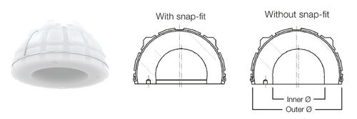
The exceptional feature of Lubinus Cup is the high cup rim, which projects beyond the spherical shape. This cup geometry reduces any luxation risk, which is further decreased by an additional snap-fit version. Another feature of the acetabular cup is its eccentric shape. This facilitates maximum material thickness in the main load-bearing zones (cranial)4.
In combination with SPII Model Lubinus Hip Stem, Lubinus Cup offers an outstanding, anatomically adapted cemented hip implant. Lubinus Cup is available in both standard UHMWPE and highly cross-linked polyethylene X-Linked.
IP Cup
The IP Cup as well as Lubinus Cup is designed with a high cup rim, which projects beyond the spherical shape. The IP Cup differs from the Lubinus Cup in integrated chamfer at the cup entrance. This gives the patient a wider range of motion due to the design where the neck of the prosthesis strikes the cup rim later.
The IP Cup is a cemented acetabular cup made of UHMWPE: both versions of IP Cup from standard UHMWPE and X-Linked UHMWPE are possible.
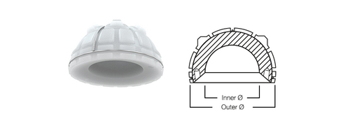
FAL Cup
Same as other cemented acetabular cups, the design of FAL Cup with vertical and horizontal grooves in the surface creates a high degree of cement contact and allows air to escape when the implant is pressed into the cement bed4 with a uniformed cement mantle. In addition, the FAL Cup has a peripheral rim, unlike the IP Cup or the Lubinus Cup. This rim increases the cement compression, which increases cup stability in the cement matle7.
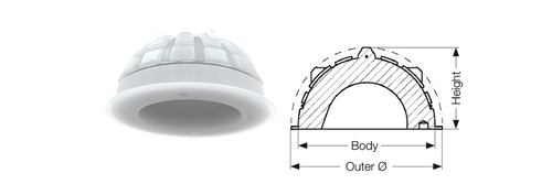
FC Cup
FC Cup has integrated high cup rim, which projects beyond the spherical shape. The FC Cup differs from the FAL Cup in integrated chamfer at the cup entrance. This gives the patient wider range of motion due to increased distance to a contact point between the cup rim and the implant neck. In addition, unlike the IP Cup and the Lubinus Cup, the FC Cup has a peripheral rim.
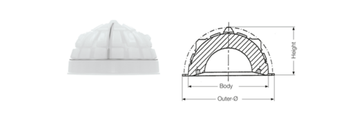
Endo-Model Cup
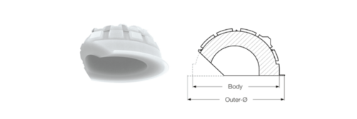
The Endo-Model Cup features an integral medioventral recess, which provides a wide range of motion and protects the femoral nerve together with psoas tendon. Psoas tendon or femoral nerve can be irritated by the cup rim in case of larger cup diameters.4 In addition, Endo-Model cup has a partial peripheral rim, unlike the IP Cup and the Lubinus Cup. This rim increases the cement compression resulting in a better cup stabilization in the cement mantle.7
Due to its anatomically adapted medio-ventral cut-out, Endo-Model Cup comes in two versions: right and left. Both versions have a circulating flange around the cup, except for the cut-out.
UHMWPE and X-Linked polyethylene
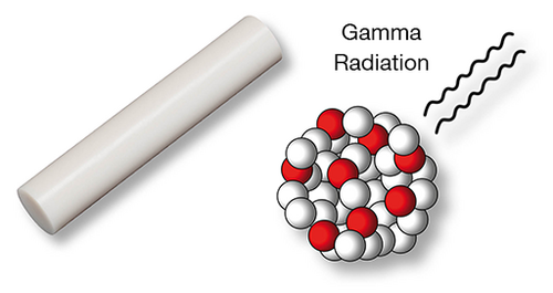
LINK has decades of experience in the use of UHMWPE and this was particularly valuable in the design of the cemented acetabular cups. The high quality of the polyethylene demonstrably minimizes abrasion suffered by the components, thereby reduces the risk of osteolysis. Consequently, the incidence of component loosening is very low. In addition to the Standard UHMWPE, we also supply the system in acetabular cups made of X-Linked UHMWPE. This highly crosslinked polyethylene makes it possible to achieve even lower abrasion levels.2, 3
In addition to the material properties, the external shape of the acetabular cups help to prevent loosening. Vertical and horizontal grooves in the surface create a high degree of cement contact and allow air to escape when the implant is pressed into the cement bed.4 Approximately 0.5 mm of play between prosthesis head and acetabular cup allows for “lubrication” by body fluids6. Furthermore, spacers on the rear surface of the acetabular cup permit a uniform cement coating. This surface design increases the stability of the cup in the acetabulum, thereby largely eliminating the risk of loosening.5 This design is used successfully in the FC, FAL, and IP as well as Lubinus Cup.
- L. Claes, P. Kirschner, C. Perka und M. Rudert, AE-Manual der Endoprothetik - Hüfte und Hüftrevision, Heidelberg Dordrecht London New York: Springer, 2012.
- S. M. Kurtz, „Advances in the processing, sterilization, and crosslinking of ultra-high molecular weight polyethylene for total joint arthroplasty“, Biomaterials 1999; 20:1659-1687.
- E. M. Brach del Prever, „UHMWPE for arthroplasty: past or future?“, J Orthopaed Traumatol 2009;10:1-8.
- H. W. Buchholz (1969), “Das künstliche Hüftgelenk”, Sonderdruck aus Materia Medica Nordmark, Nov. 1969, 21/11: 613-622
- Garellick, Kärrholm, Rogmark, Rolfson, Herberts, ANNUAL REPORT 2014; The Swedish National Hip Arthroplasty Register.; p. 75
- H.W. Buchholz und E. Strichte (engineering BASF), 1972
- W. Buchholz, Das künstliche Hüftgelenk, Modell St. Georg, in Der totale Hüftgelenkersatz, Georg Thieme Verlag Stuttgart, 1985
LINK Direct Anterior Approach (DAA)

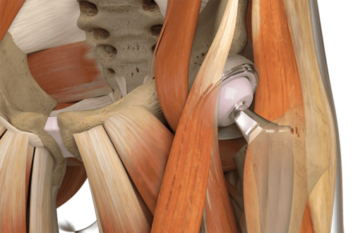
ANATOMICAL APPROACH with Anatomical Stems made by LINK
Tissue preserving approach meets bone preserving stems
- Polished tip supports easy and safe insertion1
- Integrated anteversion facilitates access to the femur
- Flattened lateral shoulder helps to preserve bone and soft tissue2
